Section 01
Start with elevation—not a screenshot of contour lines
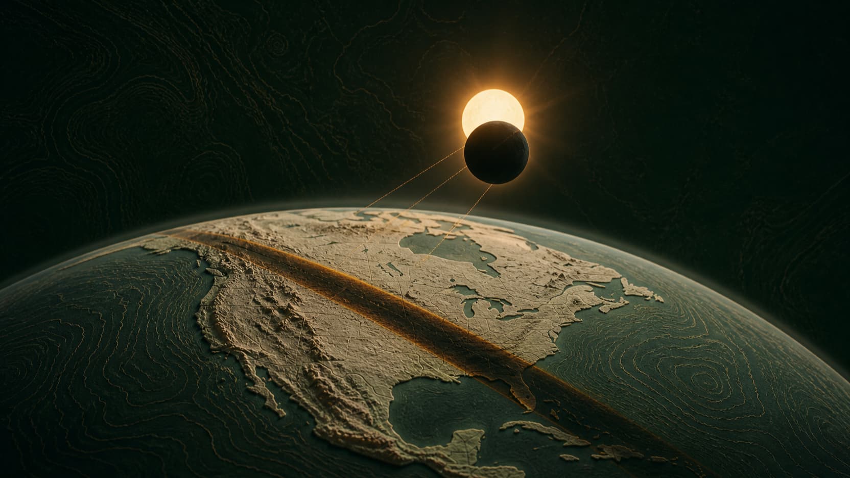
A printed topographic model needs height at many locations. A paper map communicates that height through contour lines, labels and color, but those pixels do not automatically contain a continuous surface. The underlying geometric input is usually a digital elevation model, or DEM: a grid whose cells store elevation values. A terrain generator samples that grid and connects the samples into a mesh.
This distinction prevents a common dead end. Tracing the dark lines in a map image may reproduce the graphic, but it does not reliably recover the land between the lines. Begin from coordinates and available elevation data whenever possible. Keep the map image for surface context; let elevation create the geometry that will become the printed relief.
- Contour lines describe equal elevations; they are not walls in the finished model.
- Map imagery supplies visual context, while elevation supplies shape.
- A higher-resolution source can preserve smaller landforms, but only when the source is trustworthy and the print is large enough to reveal them.
Section 02
Frame the smallest area that contains the terrain story
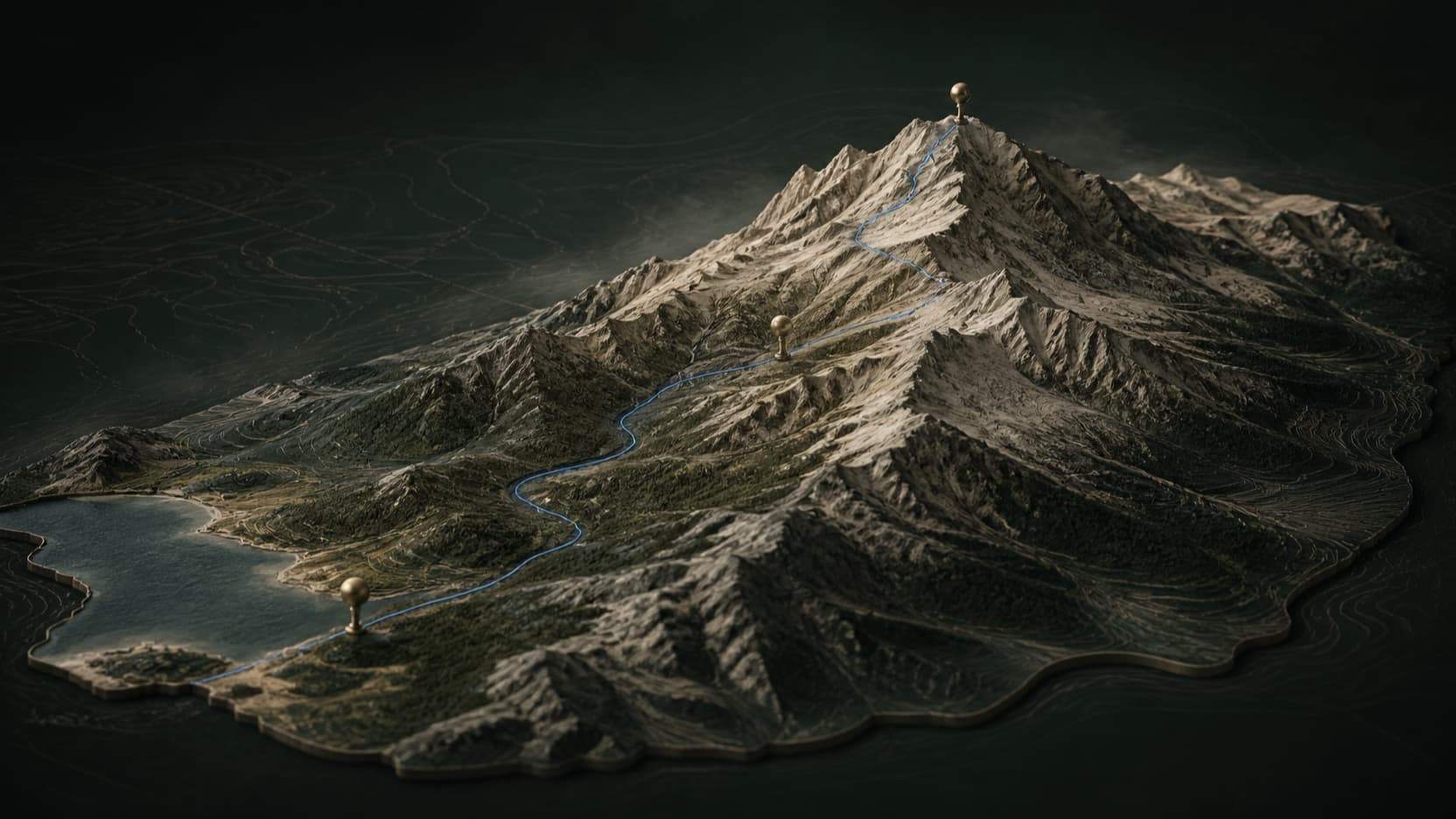
Choose the physical object before choosing the map extent. A mountain summit, watershed, island or neighborhood each needs a different frame. If the selected area is too large, the same print width must represent more kilometers and local relief becomes visually shallow. If it is too tight, the model loses the ridges, approaches or surrounding context that make the place recognizable.
Use one unmistakable geographic feature as the anchor, then leave enough margin for a stable border and base. Check the selection in 3D before committing. The decisive question is not whether every nearby landmark fits; it is whether the final object still explains the place at the size you intend to print.
Section 03
Convert the terrain surface into one closed solid
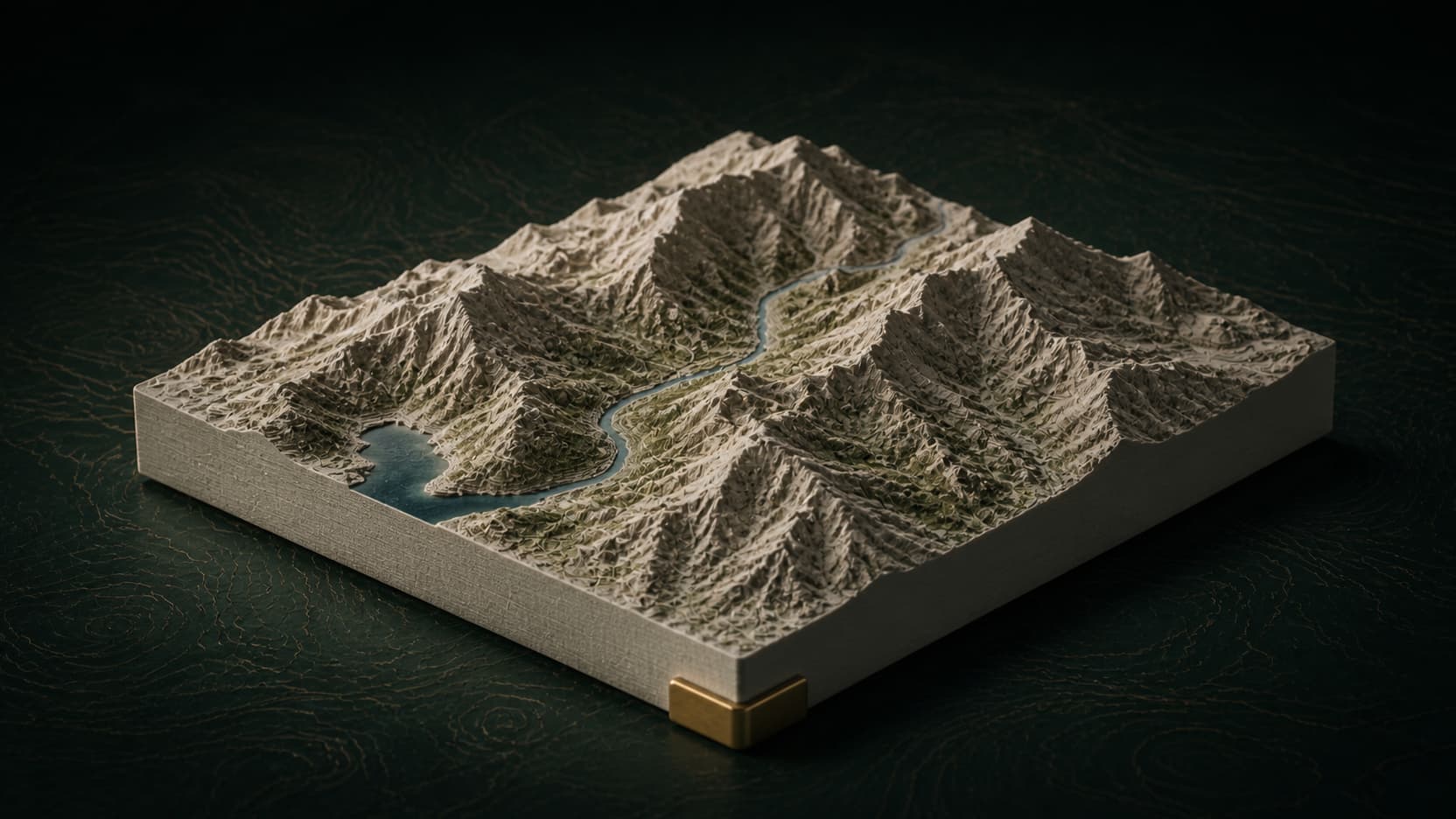
A rendered terrain mesh can be only a thin top sheet. A printer needs a volume. The printable version therefore requires the terrain top, closed side walls and a flat underside. Every boundary edge on the top must connect to the base, face orientation must remain consistent, and the combined geometry should describe one enclosed object rather than overlapping shells.
Make3DMap keeps this manufacturing handoff separate from the editable scene. The checked print export currently includes the generated terrain surface, side walls, flat underside and repaired millimeter-scaled mesh. Water, routes, pins, labels, placed objects and uploaded custom terrain remain visible in the scene but are not silently added to the print file because each would need its own union, thickness and intersection checks.
A model that looks solid on screen can still contain open edges, duplicate faces or disconnected shells. Visual inspection alone is not a print-readiness test.
Section 04
Set physical width, relief and base as one decision
The same digital terrain can become a 100 mm desk model or a 300 mm wall piece. Set the finished width first, then judge the relief and base in millimeters. Increasing vertical exaggeration makes gentle terrain readable, but too much changes the perceived slope and can produce fragile peaks. A thicker base improves handling but also increases material and print time.
There is no universal exaggeration value. Review the lowest valleys, narrow ridges and edge transitions at the intended size. The base must stay thick enough after scaling, not merely look thick in editor units. For very flat cities, a restrained exaggeration may be necessary for legibility; for steep mountains, the source relief may already be strong enough.
Section 05
Run topology and orientation checks before download
A useful export gate reports measurable geometry. Check for open boundary edges, non-manifold edges, disconnected components, degenerate or duplicate triangles, consistent orientation, positive enclosed volume and minimum base thickness at the chosen physical size. Deterministic issues such as duplicate triangles, simple boundary gaps and inconsistent face direction can sometimes be repaired automatically; the result still needs to be analyzed again after repair.
The verified Make3DMap print sample below was generated through the same browser workflow and independently re-read from both output formats. Its passing report describes one watertight solid with zero open and non-manifold edges. That proves the sample's geometry passed the implemented checks; it does not guarantee a successful print on every machine or material.
Section 06
Prefer 3MF for units; keep STL for compatibility
STL describes a surface as triangles and remains widely supported, but its geometry does not provide a dependable unit field. A model intended to be 160 millimeters wide can arrive at the wrong scale if the receiving software assumes another unit. Confirm millimeters when importing STL. The 3MF core format carries a declared model unit and packages manufacturing data more explicitly, so it is the safer default when the slicer supports it.
The file is the beginning of the manufacturing check, not the end. Open it in the exact slicer you will use, confirm dimensions and bed orientation, inspect the first layers, choose layer height and material, and decide whether the terrain needs supports. Preview the toolpath around thin peaks and steep overhangs. Print a reduced test when the model is large or the terrain is unusually sharp.
- Use 3MF when you want the millimeter unit carried with the model.
- Use STL when compatibility requires it, then confirm millimeters on import.
- Keep the source location, selected frame and export settings with the file so the terrain can be reproduced.
Evidence
Sources and further reading
Quick reference
Frequently asked questions
Can I turn a screenshot of a topographic map directly into an STL?
Not reliably. A screenshot contains visual contour information, not a complete elevation surface. Use coordinates and available elevation data to build the terrain geometry, then use imagery only as visual context.
Why does my terrain STL import at the wrong size?
STL stores triangle coordinates without a dependable unit declaration. Set or confirm millimeters in the slicer. Use 3MF when possible because it carries the model unit explicitly.
Does a watertight check guarantee the terrain will print?
No. It confirms important mesh properties, but the slicer, printer, material, supports, layer height, nozzle and terrain shape still determine manufacturability and final quality.